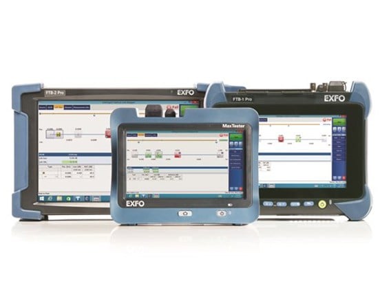
FLS-600 NS-1548 - Encircled flux compliant light source

Tier-1/2 solutions with controlled source launch conditions for maximum accuracy and repeatability designed to remove uncertainty from multimode fiber testing.
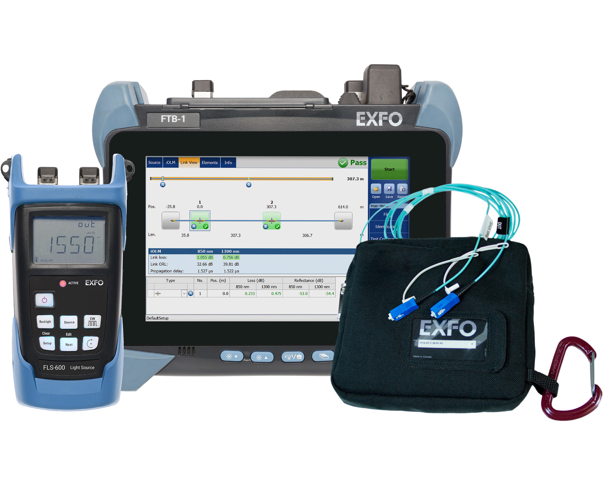
Key features

EF-compliant as per TIA -526-14-B and IEC 61280-4-1 Ed. 2.0
Optimized for multimode loss testing
Tier-1/2 testing of multimode fibers as recommended in TIA-568
Reference-grade UPC connectors for maximum precision and repeatability
Built-in EF-compliant light source—no extra equipment to manipulate

Applications

Data center/high-speed links
Enterprise and private networks

Description

Understanding encircled flux

Encircled Flux (EF) is a new standard that defines how to control the source launch conditions as specified in TIA-526-14-B and IEC 61280-4-1 Ed. 2.0.

Whether for an expanding enterprise business or a large-volume data center, the new high-speed data networks built with multimode fibers are running under tighter tolerances than ever before.

These multimode fibers are the trickiest links to test because the results depend greatly on each device’s output conditions. Testing with different equipment often returns different test results, sometimes higher than the budget loss itself. This may mislead the technician or make it impossibleto locate the fault, resulting in unsuccessful turnups or a longer network downtime. Now, cable installers can rely on their tier-1 loss results to perform tier-2 troubleshooting, and do so with maximum accuracy and utmost confidence of finding the actual problem.

Consistency and repeatability

Whether built-in or packaged in the external launch conditioner, EXFO tunes each EF-compliant device to perfection in-house, ensuring that every unit meets the EF templates for both 850 and 1300 nm at 50 μs. This allows technicians and contractors to obtain reliable, consistent and repeatable results during construction, thus eliminating doubts and uncertainty. The test documentation that is generated will also help future-proof networks. When upgrades are needed, technicians and contractors will know quickly which circuits have to be activated, thereby saving time and troubles down the line.

The necessity of launch and receive cables

Link characterization is often performed using an OTDR. However, despite the fact that an OTDR has the shortest dead zones, the way loss is measured in a link means that to characterize the first and last connectors, an OTDR needs a launch cable, also called a pulse suppressor box.

The reason for this is that the loss associated with an event is the difference between the backscattering levels measured before and after the event. To account for the dead zone, a backscattering level must be obtained before the first connector. This requires inserting a length of fiber between the OTDR port and the first connector of the fiber under test. At the other end, the same lengthof fiber is inserted after the last connector.

In order to measure the loss of the first and last connectors, it is important to use launch and receive cables. The SPSB-EF has an internal 30-meter fiber that allows complete end-to-end loss while still maintaining the EF launch conditions up to the first connector of the link. By complying with the EF standards, faulty connectors are easily located when troubleshooting high-speed multimode links.

Resources

All resources
Spec sheet
Encircled Flux (EF) test solutions - English (United States) (January 06, 2019)
Spec sheet
Encircled Flux (EF) test solutions - 中文(中国) (January 06, 2019)
Spec sheet
Encircled Flux (EF) test solutions - Deutsch (Deutschland) (January 06, 2019)
Application notes
Maximizing the Long-Term Performance of Your OTDR/iOLM by Using APC Connectors - English (August 22, 2011)
Application notes
Maximizing the Long-Term Performance of Your OTDR/iOLM by Using APC Connectors - Français (August 22, 2011)
Application notes
Maximizing the Long-Term Performance of Your OTDR/iOLM by Using APC Connectors - 中文 (August 22, 2011)
Application notes
Maximizing the Long-Term Performance of Your OTDR/iOLM by Using APC Connectors - Español (August 22, 2011)
Application notes
Maximizing the Long-Term Performance of Your OTDR/iOLM by Using APC Connectors - Deutsch (August 22, 2011)
On-site trainings
Advanced OTDR Testing - English (January 05, 2012)
On-site trainings
Advanced OTDR Testing - Français (January 05, 2012)
On-site trainings
Advanced OTDR Testing - 中文 (January 05, 2012)
Brochures and catalogs
OTDR and iOLM selection guide - English (May 20, 2019)
Brochures and catalogs
OTDR and iOLM selection guide - 中文 (May 20, 2019)
Reference guides
Distributed Antenna System—Testing Guide - English (May 12, 2013)
Reference guides
FTTH PON - English (December 12, 2011)
Reference guides
FTTH PON - 中文 (December 12, 2011)
Reference guides
FTTH PON - Español (December 12, 2011)
Reference guides
FTTH PON - Deutsch (December 12, 2011)
Application notes
Multimode Fiber Certification: Light Source Launch Conditions and Encircled Flux Standard - English (August 21, 2011)
Application notes
Reducing FTTH OPEX with the Intelligent Optical Link Mapper (iOLM) - English (August 23, 2011)
Application notes
Reducing FTTH OPEX with the Intelligent Optical Link Mapper (iOLM) - Français (August 23, 2011)
Application notes
Reducing FTTH OPEX with the Intelligent Optical Link Mapper (iOLM) - 中文 (August 23, 2011)
Application notes
Reducing FTTH OPEX with the Intelligent Optical Link Mapper (iOLM) - Español (August 23, 2011)
Application notes
Reducing FTTH OPEX with the Intelligent Optical Link Mapper (iOLM) - Deutsch (August 23, 2011)
Application notes
Touching on Failure: Sources of Fiber-Optic Network Issues in the Data Center - English (February 08, 2016)
Multimedia trainings
Web Training Series—FTB-1 and FTB-730-iOLM - English (December 14, 2011)

Support