Description
Signal transmission over fiber-optic cabling has proven its effectiveness in carrying large amounts of data, which is why optical fiber is being rolled out deeper and ever closer to the customer premises.
With the advent of 5G, fiber-to-the-x (FTTx) architectures are now the norm, laying the groundwork for the exponentially increased bandwidth required by IoT and a host of new applications. The “x” in FTTx is a variable indicating the point in the network where the fiber stops and copper cabling (coaxial or twisted pair) takes over (unless the fiber goes all the way to the home). The further the fiber goes, the wider the bandwidth, the faster the speed, and the more applications and services that can be offered.
In today’s context of FTTx network architectures, it is vital to have the right set of test tools to ensure optimal quality of service to subscribers from the get-go. If a need for troubleshooting occurs, these test tools must be able to locate, identify and fix issues while the technician in onsite to avoid repeat truck rolls.
Let’s have a look at various FTTx architectures, and see what challenges come with these network topologies and applications.
Types of FTTx networks
FTTH (Fiber-to-the-home)
Fiber-to-the-home (FTTH) means the fiber connection goes all the way to the customer premises (home or private network), and therefore provides the maximum bandwidth. However, FTTH is costly to roll out, especially when dealing with a legacy network. Replacing an existing architecture may not be advantageous for the network owner, who may opt for a different strategy. FTTH is usually the chosen architecture for greenfield projects (new builds).
Typically, for an FTTH network, the optical line terminal (OLT) interfaces with the public-switched telephone network (PSTN) and internet services at the headend (i.e., the central office). Data, voice and video services are carried simultaneously and in different directions at different wavelengths (upstream: 1310 nm | downstream: 1490/1550 nm or upstream: 1260 nm or 1270 nm for XGS-PON | downstream: 1575 nm for next-gen passive optical networks or PON or 1577 nm for XGS-PON). At 1550 nm, the optical video transmitter also converts analog radio frequency (RF) video services into optical format. The wavelength division multiplexing (WDM) coupler entwines the 1550 nm and 1490 nm wavelengths and transmits them downstream together.
An FTTH link consists of a singlemode fiber (drop cable) that exits a transmitter/receiver (optical network terminal or ONT) installed at the customer premises. The drop cable passes through at least one local PON splitter. The splitter then connects to the OLT at a central office via a multifiber cable (feeder).
From installation to activation to troubleshooting, the basic FTTH tests include: optical insertion (IL) and return loss (ORL), link mapping, power levels and connector inspection.
FTTA (Fiber-to-the-antenna)
Fiber-to-the-antenna (FTTA) is a broadband network architecture in which optical fiber is used to connect the remote radio head (RRH) to the base station in new antennas, or retrofitted in existing ones, to replace all or part of the coax local loop. Fiber-optic cables are lighter than coax cables, and therefore, easier to install. Fiber has many more advantages, including signal integrity and increased energy efficiency. FTTA is required to support low-latency, high-speed backhaul and increase traffic bandwidth.
FTTB (Fiber-to-the-building)
Fiber-to-the-building (FTTB) is an optical fiber cable that reaches the boundary of the building, such as the basement in a multidwelling unit, with the final connection to the individual living spaces being made via alternative means. Fiber distribution terminals (FDT) are used to connect every subscriber’s ONT to a fiber distribution hub (FDH). The FDH cabinet, which contains splitters, patch panels and fiber-management elements, is connected to the central office. FTTH and FTTB can both fit under the fiber-to-the-premises (FTTP) umbrella.
FTTC (Fiber-to-the-curb)
Fiber-to-the-curb (FTTC) is a topology in which the fiber runs from a central office to a curb-side distribution point, such as a in a pole or an enclosure, in the vicinity of customer premises. These distribution points are closer to the home than nodes in an FTTN network and deliver services to a smaller cluster of customers. The curb-side distribution point is connected to the subscribers via twisted-pair copper cables.
FTTN (Fiber-to-the-node)
Fiber-to-the-node (FTTN) is a network where the optical fiber ends at a street cabinet, with final connections being made through existing legacy copper or coaxial cables. Nodes can be close or relatively far away from the customer premises. For example, remote ADSL2+ DSLAM can be 3 or 4 miles away from a subscriber. FTTN is an economical way to deliver advanced triple-play telecommunications services to numerous customers from a single node, without having to roll out the fiber all the way.
FTTx network lifecycle
An FTTx network has lifecycle that consists of several phases. Upon deployment, a well-planned network will map each event and loss budgets for every link, such as splice locations, distribution patterns and splitter configurations. The fact that a connector comes directly from the factory does not prevent it from being dirty or damaged. The same goes for splices and other elements. This means that testing must be a reflex to ensure any FTTx deployment. Here are some of the methods of procedures (MoPs) and key tests that should be performed at each phase of the network cycle.
Construction or deployment phase
The following network elements need to be tested:
All connectors
With faulty connectors being the no. 1 cause of network failures, inspecting connectors can help you save money and give you the assurance that your network is healthy. Connectors are the most overlooked aspect of a network, but contamination from a wide range of sources can have a serious impact on network loss and reflectance. To make this step fast and easy, consider fully automated fiber inspection probes. Nowadays wireless options are also available.
F1/spine
This can be either an existing network or a new cable installation. This type of link should be tested normally to verify that splices are within specifications and losses are as expected.
Drop terminal/demarcation point to the central office/PoP/exchange
Ports should be inspected. Using an OTDR to characterize a network requires expertise to select the correct settings and to interpret the results. In many cases due to the proximity of optical splitters to one another and to other components, more than one measurement may be needed to fully characterize the network. Here, we recommend a testing solution that can reduce the risk of human errors by eliminating the need to configure parameters and to interpret complex multiple OTDR traces. The intelligent Optical Link Mapper (iOLM), for instance, has preset test configurations and parameters where pass/fail criteria are hardcoded for splices, connectors (for both loss and reflectance), splitter enclosure losses, overall link loss and ORL. Advanced algorithms will dynamically define the testing parameters, as well as the number of acquisitions that best fit the FTTx network under test. Results are displayed in an icon-based fiber-link view to quickly assess an event pass/fail status per standard selected. Such a solution will also cover troubleshooting from the customer side to find faults in F1 and/or F2 sections, or after the last splitter(s) up to the CO (practical for fully spliced networks). Using receive fiber at the optical distribution frame (ODF) port at the CO/PoP/exchange ensures that connectivity to that demarcation point is correct. Once all tests are completed, the OLT can be connected to the ODF and all the splitter ports at the drop terminal will go “live.”
Service activation phase
On the day of the activation, the optical power at the drop terminal should be verified. This can be done with a conventional power meter, set to 1490 nm for GPON without RF video, or with a PON power meter that will discriminate power from multiple downstream layers such as 1550-nm RF video over GPON or any combination of GPON and next-gen PON services, such as XGS-PON and NG-PON2. This will confirm that the downstream powers are within budget and that the drop cabling can be installed. Opt for power meters that can be connected in series with the ONT, allowing the ONT to communicate with the OLT, meaning that both the burst upstream and downstream power can be verified in pass-through mode, without interrupting the service.
For a quick check, an optical fiber multimeter (OFM) can be used. An OFM is an essential handheld tool for frontline fiber optic technicians., alike to well-known multimeters used for fiber optic technicians, alike to well-known multimeters used for electrical circuits. OFMs quickly measure several key optical parameters such as loss (dB), optical return loss (dB), length (meters) and power (dBm). OFMs help technicians verify the fiber optic link health and troubleshoot potential issues. EXFO has launched the first unit from this category, the Optical Explorer.
To test the ODN loss, or difference in optical power between the OLT TX and the ONT RX, consider using an FTTH and Business Services tester, such as the EX1. The tester should be capable of emulating the ONT and of providing the GPON operational status, ONU ID, ONT Optical RX power, IP address, speed test over GPON.
Once service activation is completed, verifying that the service is being delivered as expected before leaving customer premises is strongly recommended to avert unnecessary truck rolls. Running a speed test—by connecting the ONT to an independent speed tester—will provide reliable results (which is not always the case when running the test on a PC or over WiFi).
Troubleshooting and maintenance phase
One of the most important tools for this phase is an OTDR or an iOLM with a filtered port working with an out-of-band wavelength. An OTDR shooting wavelengths of 1310/1550 nm (used in construction) cannot be used to troubleshoot a live network as the OTDR will not be able to discriminate the downstream signal power from the backscattering of its own emitted pulses (this also risks burning the OTDR detector). Also, the 1310/1550-nm signal could disrupt upstream live traffic on the PON network and potentially damage SFPs at the OLT. The only solution is to use a filtered live port that will significantly attenuate any incoming traffic and allow testing to be performed without impacting services.
Testing with this port at either 1625 nm or 1650 nm will show and locate any breaks or high losses very clearly. Selecting a singlemode dual port OTDR with one port to test dark fiber (1310/1550 nm) for construction phase and a second port to test live fiber (1625/1650 nm) provides greater flexibility. Due to time constraints, many networks are built first and then tested, so having both options available allows technicians to test at any phase of the network lifecycle.
Low power or slow speeds can be diagnosed as described above with a power meters or a test and monitoring solution, by cross-referencing results obtained during subscriber activation phase.
Saving time and money at every phase
Leveraging cloud-based workflows, managers will be able to predefine and assign jobs that will automatically sync with field test equipment, significantly reducing the time spent by field technicians on administration tasks while minimizing data entry errors. Look for end-to-end field test management solutions that include reporting capabilities, automated close-out packages and batch validation, as well as insightful analytics, such as TestFlow.
Tapping into the power of the cloud for your workflow will ensure full compliance of your methods of procedures (MoPs), closing jobs and making invoicing faster while getting insights for informed business decisions.
What does the future hold for FTTx?
With unprecedented changes across the globe, with more people working remotely, more videoconferencing and more video consumption, IoT and new 5G-propelled applications on the horizon, the need for speed is astounding. FTTx networks represent the solid fiber foundation of efficient 5G deployments, and are therefore critical in moving forward. The future is fiber, and it is now.
EXFO’s remote fiber testing and monitoring (RFTM) solution enables service providers and their contractors to build high quality fiber optic networks right from the start, reducing costly rework and enabling faster activation and monetization. Featuring the fastest HRD testing on the market, highly scalable test head deployment and an intuitive mobile app, the cloud-native RFTM solution is OPEX- and CAPEX-efficient. It provides full visibility of the built network and delivers a single source of truth that speeds troubleshooting.

Equipped to face the fiber future?
As technology transforms the world, the field crew that is properly equipped to deploy FTTx right the first time, wins the game.
Related products
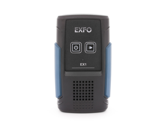
EX1 - solución de prueba y monitoreo
Solución de prueba de plataforma abierta y escalable para validar la velocidad de ancho de banda y supervisar el rendimiento de la red
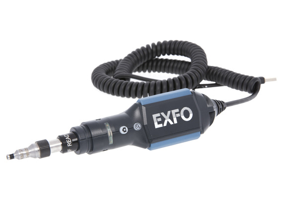
FIP-400B USB - sonda de inspección de fibra
La primera sonda de inspección de fibra completamente automatizada diseñada para pruebas de campo. Esta herramienta de prueba inteligente y automatizada transforma la inspección de fibra en un proceso de un paso más rápido y simplificado, que brinda resultados de pruebas precisos y consistentes, y e
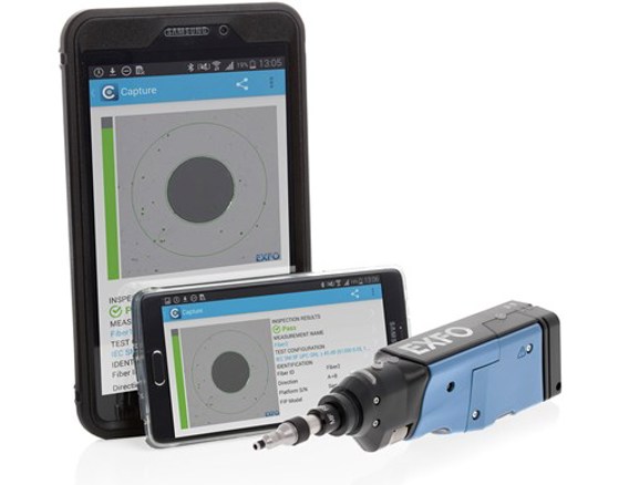
FIP-400B Wireless - sonda de inspección de fibra
Convierta su dispositivo Android™ o iOS en una solución de inspección de fibra completamente automatizada que brinda resultados de pruebas rápidos y consistentes. Sin cables en medio de su camino ni baterías incómodas, le ofrece una inigualable experiencia de usuario final, junto con portabilidad para llevarlo a donde quiera.

FLS-240 Pocket Pal - Localizador visual de fallos
Solución directa para identificar roturas, curvaturas, conectores o empalmes defectuosos, así como otras causas de pérdida de señal.

FTBx-730C - PON FTTx/MDU OTDR
Seamlessly characterize splitters in PON FTTx and MDU applications.
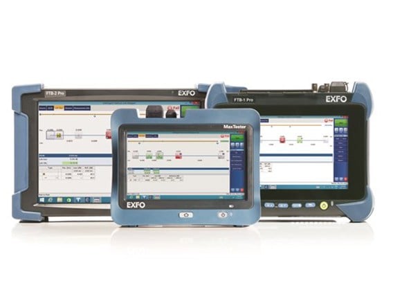
iOLM - asignador de enlace óptico inteligente
Pruebas de fibra de uno y varios modos automatizada a nivel de expertos que elimina la necesidad de configurar manualmente los parámetros o analizar e interpretar múltiples seguimientos complejos del OTDR
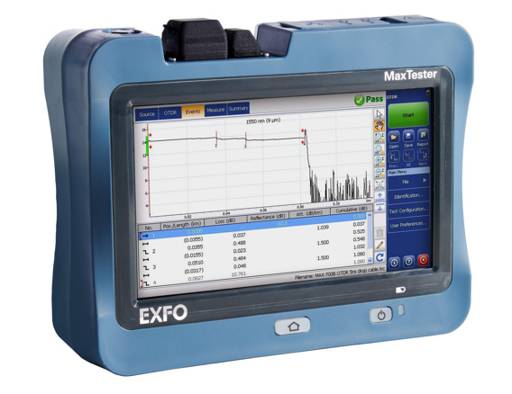
MaxTester 730C - PON/OTDR urbano
OTDR dedicado y básico con funciones completas y un diseño inspirado en las tabletas adecuado para zonas urbanas y optimizado para pruebas con divisores ópticos para una resolución de problemas y caracterización fluidas e integrales de la FTTH.

MaxTester 945 - fiber certifier OLTS
Optimized for Tier-1 fiber certification (data center, enterprise) and designed to help installation contractors, network engineers and IT maintenance technicians achieve faster, first-time-right-system acceptance

MaxTester 945 - Telco OLTS
First tablet-inspired, multifunction optical loss test set (OLTS) delivering insertion loss, optical return loss and fiber length measurements at two wavelengths in five seconds via fully automated bidirectional FasTesT™ analysis.

MPC-100 - optical power checker
This micro optical power checker brings optical testing capability to your Android™ or iOS smart device.
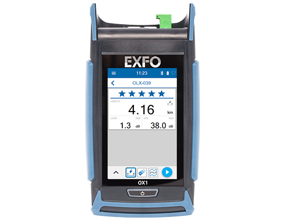
Optical Explorer - el primer multímetro para fibra óptica de la industria
Comprobador de fibra óptica que verifica los enlaces y realiza el seguimiento automatizado de anomalías en segundos permitiendo a los técnicos de primera línea hacer una exploración en profundidad.

PPM-350D - medidor de potencia PON de última generación
El primer medidor de potencia PON-aware™ que permite detectar y probar de manera automática tecnologías PON de última generación y heredadas.
Resources
All resourcesLanguage
Resource type


